

Hey there! As a supplier of Ultrasonic Cleaner Electronic Circuits, I've seen firsthand how crucial it is to design a comprehensive protection circuit for these devices. In this blog, I'll share some insights on how to do just that.
Understanding the Basics of Ultrasonic Cleaner Electronic Circuits
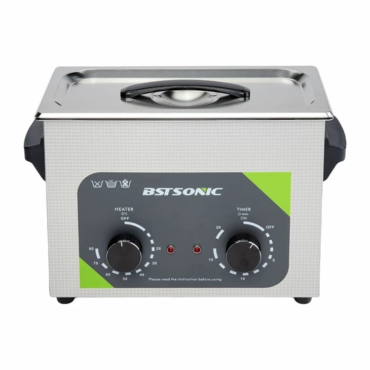
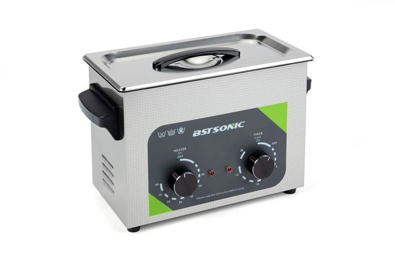
Before we dive into protection circuits, let's quickly go over what an ultrasonic cleaner electronic circuit does. Ultrasonic cleaners use high - frequency sound waves to create tiny bubbles in a cleaning solution. These bubbles collapse, creating a scrubbing action that can remove dirt and grime from various objects, like Ultrasonic Cleaner Sunglasses or Ultrasonic Cleaner for Fishing Reels.
The electronic circuit is responsible for generating the high - frequency signals that drive the ultrasonic transducers. It typically consists of an oscillator, amplifier, and power supply. But these components are vulnerable to various issues, which is where the protection circuit comes in.
Common Risks in Ultrasonic Cleaner Electronic Circuits
There are several risks that can damage an ultrasonic cleaner electronic circuit. Overvoltage is one of the most common problems. If the input voltage is too high, it can fry the sensitive components in the circuit, such as the transistors and integrated circuits.
Overcurrent is another risk. When too much current flows through the circuit, it can cause overheating, which may lead to component failure. Short - circuits can also occur, either due to a manufacturing defect or damage to the wiring. A short - circuit can cause a sudden surge of current, which is extremely harmful to the circuit.
Thermal issues are also a concern. The power - consuming components in the circuit, like the amplifier, generate heat during operation. If this heat is not dissipated properly, it can increase the temperature of the components, reducing their lifespan and potentially causing malfunctions.
Designing a Comprehensive Protection Circuit
Overvoltage Protection
To protect against overvoltage, we can use a voltage regulator. A voltage regulator is a device that maintains a constant output voltage, regardless of the input voltage fluctuations. For example, a linear voltage regulator can be used to step down the input voltage to a safe level for the circuit.
Another option is to use a transient voltage suppressor (TVS) diode. A TVS diode is designed to conduct a large amount of current when the voltage across it exceeds a certain threshold. It can quickly clamp the voltage to a safe level, protecting the circuit from voltage spikes.
Overcurrent Protection
For overcurrent protection, a fuse is a simple and effective solution. A fuse is a small device that contains a metal wire. When the current flowing through the fuse exceeds its rated value, the wire melts, breaking the circuit and preventing further damage.
A circuit breaker can also be used. Unlike a fuse, a circuit breaker can be reset after it trips. It works by using a switch that opens when the current exceeds a set limit.
Short - Circuit Protection
To protect against short - circuits, we can use a current - limiting resistor. A current - limiting resistor is placed in series with the circuit. It restricts the amount of current that can flow in the event of a short - circuit, preventing excessive current from damaging the components.
We can also use a short - circuit protection relay. This relay monitors the current in the circuit and disconnects the power supply if a short - circuit is detected.
Thermal Protection
Thermal protection can be achieved by using a thermal sensor, such as a thermistor. A thermistor is a type of resistor whose resistance changes with temperature. When the temperature of the circuit exceeds a certain threshold, the resistance of the thermistor changes, which can be used to trigger a cooling mechanism or shut down the circuit.
Heat sinks can also be used to dissipate heat. A heat sink is a device that transfers heat from the hot components to the surrounding air. It usually has a large surface area to increase the rate of heat transfer.
Testing and Validation
Once the protection circuit is designed, it's important to test and validate it. We can use a power supply with adjustable voltage and current to simulate different operating conditions. For example, we can gradually increase the input voltage to test the overvoltage protection and measure the output voltage to ensure it remains within the safe range.
We can also use a load resistor to simulate a short - circuit and check if the short - circuit protection mechanism works as expected. Thermal testing can be done by monitoring the temperature of the components during operation and verifying that the thermal protection system activates when the temperature exceeds the limit.
Integration with the Main Circuit
The protection circuit needs to be integrated seamlessly with the main ultrasonic cleaner electronic circuit. It should not interfere with the normal operation of the circuit. For example, the voltage regulator should not introduce excessive noise or distortion to the high - frequency signals.
The components of the protection circuit should be carefully selected to ensure they are compatible with the main circuit. The layout of the printed circuit board (PCB) also plays an important role. The protection components should be placed close to the components they are protecting to minimize the length of the wiring, which can reduce the risk of interference.
Benefits of a Comprehensive Protection Circuit
A well - designed protection circuit offers several benefits. First of all, it increases the reliability of the ultrasonic cleaner. By protecting the circuit from various risks, it reduces the likelihood of component failure, which means fewer repairs and replacements.
It also improves the safety of the device. Overvoltage, overcurrent, and short - circuits can pose a fire hazard. The protection circuit helps to prevent these dangerous situations, making the ultrasonic cleaner safer to use.
In addition, a comprehensive protection circuit can extend the lifespan of the ultrasonic cleaner. By reducing the stress on the components, it allows them to operate under more favorable conditions, which can significantly increase their longevity.
Conclusion
Designing a comprehensive protection circuit for an ultrasonic cleaner electronic circuit is essential for ensuring its reliability, safety, and longevity. By addressing the common risks such as overvoltage, overcurrent, short - circuits, and thermal issues, we can protect the sensitive components in the circuit and prevent costly damage.
If you're in the market for a high - quality Ultrasonic Cleaner Electronic Circuit, we're here to help. Our circuits are designed with comprehensive protection features to ensure optimal performance and durability. Whether you're using the ultrasonic cleaner for cleaning sunglasses, fishing reels, or other items, our electronic circuits can meet your needs. Feel free to reach out to us for more information and to discuss your procurement requirements. We look forward to working with you!
References
- Horowitz, P., & Hill, W. (1989). The Art of Electronics. Cambridge University Press.
- Boylestad, R. L., & Nashelsky, L. (2002). Electronic Devices and Circuit Theory. Prentice Hall.